How to Draw Footing Plans
Instructions
 Then… You're ready to beginning that addition, y'all take received the plans from your architect or draughtsman but you tin't brand head nor tail of them.
Possibly this section tin help to enlighten you just a niggling chip.
On the adjacent page is a list of the plan drawings with explanations.
Working Plans are a set of plans from which the builders and other trades refer to and work off throughout the construction of the projection.
The working plans are also the plans that are submitted to the local edifice authority (along with any other documentation that might be required) when applying for a edifice permit.
A few sets of plans are usually required, two or three for the building authority when applying for let and a varying number of sets to transport out to tradesmen and building supply stores when seeking quotations.
No work can commence until such fourth dimension as the relevant authority has given approval.
An canonical (stamped) copy of the plans must be kept on the job at all times throughout structure. The building inspector will sign the canonical plans every time he does an inspection. All required inspections volition exist listed in the documentation accompanied with the approved plans.
Buildeazy has drawn up a unproblematic set of working plans to explain the bits and pieces.
The plans are for an addition to a fictitious firm.
Plan and permit requirements vary from place to place.
If contemplating drawing up your own plans or doing whatsoever building work enquire at your local building department to discover out what specific needs are bound by local building lawmaking or by local authority in order to obtain a building allow.
The example plans in this commodity are for a 34sq metres (366 sq ft) addition to a fictitious house.
Structure is concrete slab floor, brick veneer, lumber frame and lightweight tile roof on lumber trusses.
Instructions continued
Working Plans
normally contain of the post-obit:
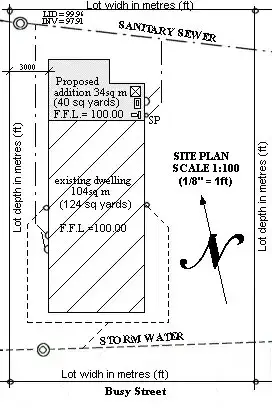
Site plan:
The site plan (plot plan) shows the placement of the existing building and the proposed addition.
The site plan too shows the site boundaries, location of services (storm h2o, sewer etc.) and relative levels of floor, finished basis and services. Contour grids showing the rise and autumn of the country are needed for sloping sections.
Example and explanation of a site plan – Page 3
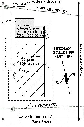
Foundation or Footing program:
The foundation or footing program shows the outlay and measurements of the foundation / footings and any required steel reinforcing.
Example and explanation of a foundation plan – Page 4
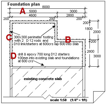
Elevation plan:
The elevation plan is more than like a cartoon of the outside of the addition rather than a program although is still drawn to scale. The height programme gives a adept perspective of the improver to the untrained middle.
Instance and caption of an tiptop programme – Page 5
Floor programme:
The flooring plan (footprint) shows the layout of the walls, too where the doors and windows are along with the sizes of the doors and windows, units such as vanities, baths etc and the designated uses of the rooms. The floor plan is to scale and walls etc are dimensioned.
Case and caption of a floor program – Page six
Roof programme:
The roof plan shows a flat plan view (looking downward view) of the layout of the roof, and where the trusses / rafters etc are situated.
Example and explanation of a roof plan – Page vii
Bracing plan:
The bracing plan shows where the wall braces go and what type of bracing is required.
Instance and caption of a bracing plan – Page eight
Cross section plan and detail instance:
The cross section plan is a plan taken from a cantankerous section of the flooring plan. The cantankerous section line is marked by flags. The cross department shows structure, lumber sizes and room heights.
A detail plan is a blow up (magnified) part of the programme to give clearer detail.
Example and explanation of a cross department plan and detail – Page 9
Specifications:
Specifications give a description of all the materials used, sizes, spacings etc and in some cases right downwardly to what type of paint to use and how many coats.
Sometimes the specifications are on a separate document but sometimes (mainly smaller jobs) the specifications are incorporated in the plan drawings.
Site Plan
Site plan:
This site program shows the placement and size of the proposed add-on along with the tempest water and sewer services. This plan also shows where the new sewer services volition connect into the existing line and the finished floor level (F.F.L.) in relation to the sewer manhole hat and sewer invert.
The plan is drawn to scale and includes boundary measurements plus the distance from the proposed addition to the boundary.
Foundation programme
Foundation programme:
A: in the drawing above
These measurements mark the footings.
In this case the superlative line shows the overall measurement of the building width, the middle line shows the overall measurement of the building recesses and the bottom line shows where the concrete blocks go.
B: in the drawing in a higher place
These lines show where the block work and footings go. The continuous directly lines marking where the 200mm (8″) concrete blocks go, and the continuous dotted lines mark where the 300mm (12″) wide footings become, 50mm (ii″) each side of the concrete block line.
C: in the drawing higher up
"300×300 (12″x 12″) perimeter ground with two D12 rods (ii #4 rebar) and D10 (#three rebar) link/starters at 600crs (24″ O.C.) lap 600 (24″) into slab"
This means the footing will exist continuous and 300mm (12″) wide and 300mm (12″) deep. The dotted lines on the programme marks the outline of the footing. Ii D12 rods (#4 rebar) run the length of the footing and are tied with necktie wire to D10 (#3 rebar) link/starters spaced every 600mm (24″) apart. The D10 (#iii rebar) link/starters must lap into the concrete slab at least 600mm (24″). For a improve agreement take a await at the cantankerous-section plan
Note: D12 rod ways deformed steel 12mm thick. That is metric. The equivalent in royal (USA) is #4 rebar, which is 1/ii″ thick.
D: in the drawing above
"Drill & epoxy 700 (28″) long D12 (#4 rebar) starters 100mm (4″) into existing slab and foundations at 600crs (24″ O.C.)."
This means drill 12mm (ane/2″) holes at least 100mm (four″) deep into the side of the existing concrete slab every 600mm (24″) apart. Glue into the holes (with epoxy) 700mm (28″) long pieces of deformed 12mm (1/2″) thick steel. This ties the new concrete footings and concrete slab to the existing.
Note:
Steel rods (D12, D10 etc) can be purchased from nearly major building suppliers and comes in six metres lengths. Steel benders and cutters can be hired from most hire firms.
Note:
In USA steel rods are called rebars and a D12 would be the same equally #four rebar which is ane/2″ thick. #ii=ane/iv″, #3=3/8, #4=i/2″ then on in increments of 1/8″ for every #1.
Elevation program
Elevation programme:
The elevation plan is more like a drawing of the exterior of the addition rather than a plan although is still drawn to scale. The tiptop plan gives a good perspective of the add-on to the untrained eye. Also a visual thought of how the land slopes.
Floor plan
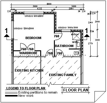
Floor programme:
The floor plan (footprint) shows the layout of the walls, too where the doors and windows are along with the sizes of the doors and windows, units such every bit vanities, baths etc and the designated uses of the rooms.
The floor programme is to scale and walls etc are dimensioned.
Dimensions:
The dimensions given are overall external walls (building line), internal room measurements from wall to wall, thickness of walls external and internal.
Flags:
The pointed things in the above program with number 1 on top of them. This marks the signal of the cross section plan.
Doors:
The door widths marked on the floor programme are the bodily width of the door and does not have into account the door jambs or whatsoever play. For a door with standard jambs add another 50mm (2″) to the plan size for the opening.
Windows:
The window (aluminum) measurement on a flooring plan is the box size. That is the exact size of the outside of the timber reveals or jambs surrounding the window, so therefore the frame opening needs to be 10mm (3/viii″) bigger than the window size on the plan.
For instance, one of the window measurements in the above plan is 600×2200. (24″x 88″) This ways the window is 600mm (24″) high and 2200mm (88″) broad so the opening built into the frame (trim size) needs to exist 610mm (24 3/8″) loftier x 2210mm (88 3/eight″) wide.
Roof plan
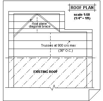
Roof plan:
The roof plan shows a flat programme view (looking downwardly view) of the layout of the roof, and where the trusses / rafters etc are situated, along with any roof bracing requirements.
Bracing program
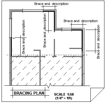
Bracing plan:
The bracing plan shows where the wall braces go and what type of bracing is required.
Cantankerous-section plan
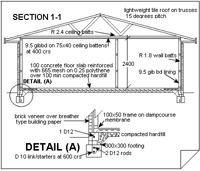
Cantankerous-section programme:
The cross section plan is a program taken from a cross section of the floor plan. The cantankerous section line in the floor plan is marked past flags.
The cross section programme shows construction, timber sizes and room heights and also a lot of specification data.
A detail plan is a blow up (magnified) function of the program to give clearer item.
Source: https://www.buildeazy.com/read-and-understand-plans/
0 Response to "How to Draw Footing Plans"
Post a Comment